WAN/LAN

Wireless Access Network / Local Area Network

What is Outdoor WIFI

- Posted in WAN/LAN by

enter image description hereWhat is Outdoor WiFi or Long-Range WiFi Network?

Outdoor WiFi are low-cost setups that can help improve your internet connection throughout your property; This set up gives you the ability to access a network from miles away - whether it’s to share the internet connection with another building or simply extend the WiFi signal outside.

To provide outdoor WIFI to an area adjacent a building, there are two approaches:

1) exterior, weatherproof, purpose-built access points, mounted on the outside of the building.

2) interior access points mated with exterior antennas. The AP is inside the building; the antenna is outside.

Often, you will choose an AP or antenna with a sector radiation pattern that directs coverage away from the building and out into an open space.

The AP or sector antenna might create a 30, 45, 60, 90, or 120 degree horizontal wedge. The narrower the antenna pattern, more concentrated the power from the transmitter. This concentration is expressed as the antenna's gain factor. An antenna with a narrow sector pattern can provide service for many miles over a smaller coverage area.

In the US, the effective radiated power output is limited to 100 milliwatts, by law. When you pair an antenna with an access point, you will have to program a gain factor for the antenna. This will be provided by the antenna manufacturer. The gain value tells the transmitter to reduce output power to remain within the law.

Antenna extension cables and connectors can cause losses between the transmitter and the antenna. With long antenna cables, you may have to reduce the programmable gain to make up for the losses. It is better to extend the Cat5e or Cat6 data cable that provides data and power to the access point than to extend the antenna leads.

When choosing a location for an exterior antenna or AP, it is best that there be line-of-sight between the antenna and the area to be covered. Trees and other structures will attenuate radio signals, particularly for the 5 GHz bands.

It is also very important that the near-field of the signal be unobstructed. Roof edges, building overhangs and corners can interfere with the radiation pattern.

Picture a pebble dropped into the water. Ripples will radiate evenly in all directions. Now, picture the same pebble dropped into water with rocks. The ripple pattern will be disturbed by the reflections from the obstructions. We want to avoid the same kind of reflections with WiFi.

To cover an open space with many access points, such as a quadrangle, it is better to mount the antennas high and aim them downward, toward the ground. This is the same approach that one would take if installing outdoor lighting, careful to light each area independently.

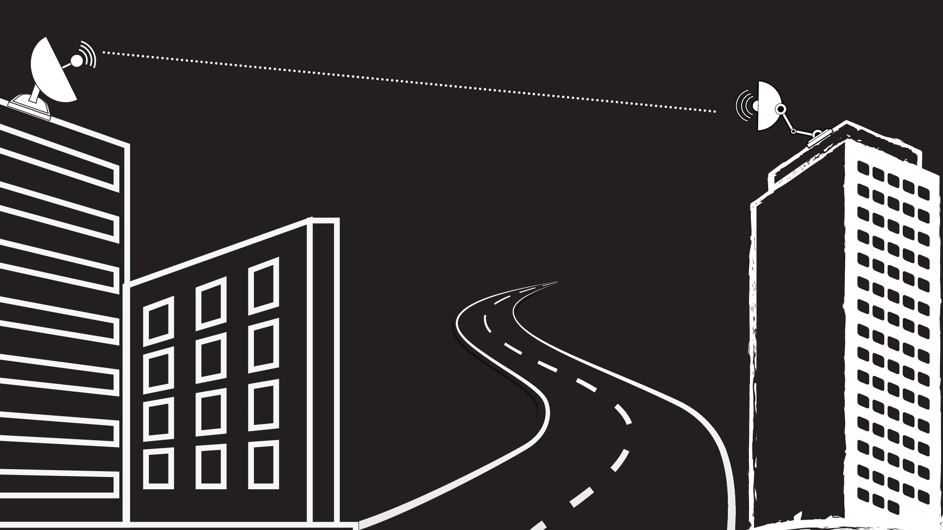
To provide WiFi to locations far away, a wireless bridge or mesh may be desired. An access point located on a building can create a back-haul link to a distant access point or access points.

When there is one access point at the far end of the back-haul link, we call this a point-to-point connection or bridge. When there are several, we call this point-to-multipoint or mesh. The distant access points may provide local service as if they were wired.

Often, with a dual-radio access point, one radio is used for the back-haul network. The other is used to provide WiFi access. Sometimes, you will use a high gain antenna for the back-haul radio and an omni-directional antenna for user WIFI. You may also let down a wired connection for a camera or switch.

There must be electrical power available at the far end of the link. This can be hard-wired AC power or provided by a power injector depending on the AP and the application. A typical access point plus camera installation will include two power injectors--one for the AP and one for the camera.

In an WiFi infrastructure, APs that form the bridge or mesh are managed by a wireless controller or cloud just as the campus APs are. Sometimes, instead, an inexpensive third-party bridge can be used to extend the campus network. Devices located at the far end, including access points, will not be aware of the third-party wireless bridge.

A typical bridge or mesh configuration will use a 5 GHz link for back-haul and 2.4 GHz for local service. The expected speed in a nearby, line-of-sight application is often just over 100 mbit/S.

Bridge and mesh products that use 24 GHz or 60 GHz radios are also available. These feature back-haul speeds that in the 1 gbit/S range. The wavelength of a 60 GHz signal is just 5mm, which is less than the width of a large raindrop or a snowflake. Because of this, 24 GHz and 60 GHz transmissions are subject to 'fade' or failure in rain, snow or fog. For this reason, 60 and 24 GHz bridges are often packaged with 5 GHz fall-back radios.

A bridge built from 900 MHz radios can penetrate trees and weather much better than a 5 GHz radio, but with much narrower channel width, measured in 100s of kbits/S.

Local outdoor coverage, bridges or meshed links--Atlantic has been providing commercial WiFi for 15 years. Call us for your next project. - Kevin Dowd
What is OFDMA, and how it will affect your WiFi?

- Posted in WAN/LAN by

The capabilities of infrastructure WiFi reliably precede the capabilities of the devices that use it, including laptops and phones. A previous major standard for WiFi, 802.11ac, included mechanics for Multi-User MIMO, or MU-MIMO. It provided a way to send data to two clients at once by adjusting power on multiple antennas. The signal that reached first client would be canceled for the other, and vice versa; one transmission, two different interpretations.

The access point that can craft a MU-MIMO transmission is a functionally a supercomputer. The transmission is the product of matrix calculations that factor in gains and the constructive/destructive interferences experienced at each client. MU-MIMO is uber-cool, except that there are still very few clients for it (five years later), and the opportunity to employ it comes only once-in-a-while.

Access points you would buy today are based on next standard, 802.11ax or WiFi 6. MU-MIMO is still part of the mix, but there is a much more interesting multi-user capability in the standard, called Orthogonal Frequency-Division Multiple Access (OFDMA). It works by sharing sub-carriers in a transmission between multiple client devices.

What are sub-carriers? At WiFi’s higher modulation rates, transmitted data are conveyed in multiple, bonded streams which are transmitted at neighboring frequencies. These are reassembled on receipt. Sub-carriers are orthogonal, meaning that the transmission of one does not interfere with the transmission of another. Sub-carriers provide a way to slice WiFI bandwidth into resilient pieces of modest width. Narrower bands can be demodulated and bonded more easily than if the whole channel were taken altogether at once. Fatal interference within a sub-carrier doesn’t necessarily ruin the transmission.

In WiFi 6, the sub-carriers can be shared so that some are destined for this client; some are for that client. This means that in one transmission, an access point can talk to multiple clients. That would be significant enough, but the real performance benefit comes from the elimination of overhead.

To make a single transmission, a modern access point has to perform channel assessment (to see if the air is busy). It has to insert guard bands (dead air) to allow for response turnaround. And, an access point has to contend with overlapped transmission, back-off and retry. The overhead time associated with acquiring the channel can be much greater than the data transmission window. This makes the air-time efficiency of a very fast access point with typical client data be about 10%. That’s low! By combining the data for multiple clients on multiple subcarriers, the efficiency can increase dramatically. The same amount of channel acquisition time can be shared among multiple users. The problem, as ever, is that there are few clients for OFDMA as of yet.

-Kevin Dowd

BSS Coloring in WiFi 6

- Posted in WAN/LAN by

BSS Coloring in WiFi 6

If you’ve ever used a two-way radio or walkie-talkie, you’ve probably had the experience where the person you’re listening to gets “stepped on” by somebody else’s transmission. You may have also noticed times when the person you’re listening to “steps on” someone else’s transmission, overpowering it.

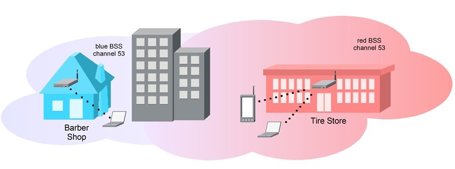
WiFi networks have long dealt with the same issues, avoiding the “stepped on” transmission by performing channel assessments and signaling intent to use a channel. This coordination and cooperation even happens between WiFi networks that otherwise have no connection to one another. If the barber shop runs an AP on channel 53 and the tire store also runs on channel 53, the two are going to share the channel. The tire store AP has its clients; the barber ship AP has its clients. Their access points and clients will each listen for the transmissions on channel 53, yielding access if the power of any transmission is above a modest -82 dbm.

In each case, the AP and its clients form a Basic Service Set, or BSS. To make better use of shared channels, WiFi 6 (802.11ax), introduces the notion of BSS coloring. The ‘color’ is a small integer in the transmission preamble. For the sake of our discussion, lets say that the integers actually correspond to colors; the BSS of the AP and all of the WiFi clients in the barber shop is blue; the tire store BSS is red. BSS color makes it immediately possible for all WiFi devices to tell whether a transmission is meant for the tire store or the barber shop.

enter image description here

BSS coloring facilitates “stepping on” another BSS’s traffic. If the AP in the tire store (red) wishes to transmit while a device in the barber shop is talking (blue), it can make a decision to broadcast over the ongoing transmission, even if the power is as high as -62 dbm. The reason this will work is that each BSS and its clients are in proximity to one another and the interference caused by its neighbors is dynamically judged to be low enough to permit the simultaneous transmission to succeed. One channel; two transmissions.

The benefit of BSS Coloring is that we can build denser WiFi networks with more channel overlap. BSS Coloring is one of the powerful new capabilities in WiFi 6.

  • Kevin Dowd

Fun with DFS

- Posted in WAN/LAN by

We have a customer who complained that every day, just before noon, users would lose their WiFi. The customer was located on a flight path for a nearby airport and military installation. As it turned out, an interim wireless firmware release changed their 5 GHz channel plan to include some Dynamic Frequency Selection (DFS) channels. These DFS channels are shared with aviation and weather radar with the proviso that if an access point detects radar on the same 5 GHz channel it serves, then it must abandon the channel. So for this customer, every day at the same time, an overhead flight knocked out part of their WiFi!

Of the twenty-two, 20 MHz, 5 GHz WiFi channels in the United States, thirteen of them are DFS channels. Because DFS channels are subject to abandonment, WiFi equipment ships with DFS channels disabled. Most WiFi systems apportion the remaining nine non-DFS channels between access points with limited contention, but there are situations where the DFS channels can solve big problems.

For example, we have a scholastic customer with some lightly built dormitories of wood-frame and gypsum. The dorms are loaded with APs. Additionally, the dorms are situated in an open space with many scholastic buildings and green space-WiFi around them. Standing next the dormitories, one can ‘hear’ forty radios. The air is busy! Adding more APs offers diminishing returns as the infrastructure competes with itself for channel access; the nine 5GHz channels are oversubscribed.

In another case, a customer had some new LED lighting installed over the summer. In the fall, they complained WiFi was intermittent on the 5 GHz band. We took measurements. The new lighting appeared to be blowing raspberries on the unlicensed 5 GHz spectrum; whatever the communication method, the LED lighting wasn’t speaking 802.11 protocols, so the WiFi infrastructure couldn’t work with it. The result was a bad WiFi experience.

In both cases, what we did was turn up some DFS channels. In the second case, we also turned down non-DFS channels. Here’s the method for enabling DFS: enable a few channels at a time. Doing it in pairs makes sense. Choose channels that can be bonded for 40 MHz. Then, watch the logs for a day or so. Look for channel abandonment events. If you don’t see any, move on to the next batch of channels. In the end, you will have an expanded collection of 5 GHz channels for your area and more available WiFi bandwidth.

We’re cowboys, here, by the way. In our office, all we use are DFS channels. So far, no deleterious effects!

-Kevin Dowd